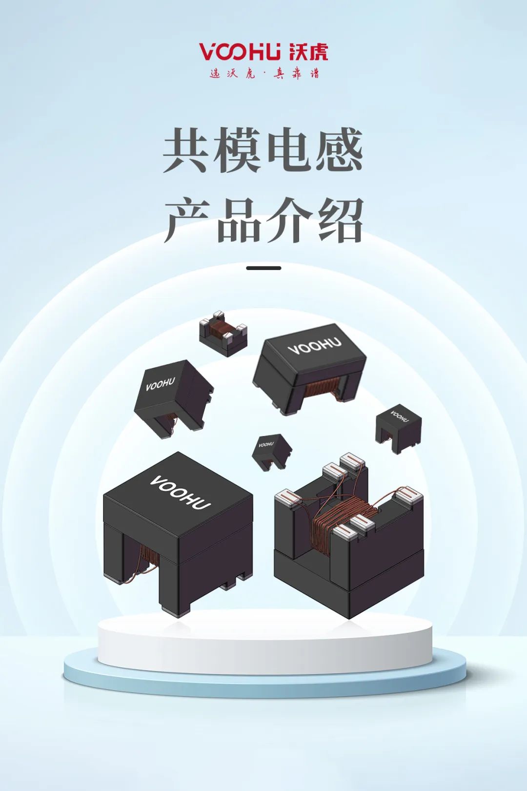
Secondary Tap GND Wiring Strategy
Transformer secondary center tap GND grounding strategy: digital signal ground vs. chassis ground
——Key points of EMC and noise suppression design of servo drive system
introduction
In the design of servo drive system power supply, the grounding selection of the transformer secondary center tap directly affects the system electromagnetic compatibility (EMC), signal integrity and safety. Based on the needs of industrial scenarios, this article analyzes the physical mechanisms of different grounding strategies and compares their effects through measured data.
1. The physical meaning of the secondary intermediate tap
The center tap (CT) is often used in full-wave rectification (such as dual-diode rectification) in rectification and filtering circuits. Its grounding method determines the discharge path of high-frequency noise.
Key parameters affecting:
- &Common-mode noise path: The center tap acts as a "virtual midpoint" for high-frequency noise, directly affecting the direction of common-mode current flow
- &Ground loop impedance: The choice of grounding point changes the noise loop impedance, which in turn affects conducted emissions (CE) and radiated emissions (RE)
2. Effect Analysis of Digital Signal Ground (DGND)
1. Connection method
Connecting the center tap directly to the digital ground plane of the PCB is common in low-cost or space-constrained designs:
CT → DGND (PCB ground plane)
2. Advantages
- &Simplified wiring: no need for additional isolation devices, reducing the number of PCB layers
-  Suppress differential mode noise: Good filtering effect for low frequency (<100kHz) switching noise
3. Defects and risks
- &Common-mode noise coupling: High-frequency noise (such as MHz-level interference caused by IGBT switching) is coupled to the signal loop through the ground plane
Measured data: When a 400V servo drive is connected to DGND, the peak-to-peak value of the CAN bus common-mode noise reaches 1.2V (exceeding the ISO 11898-2 limit)
- &Ground potential rise: Large current transients cause local DGND potential fluctuations, causing ADC sampling errors
Case: Position data jumps due to DGND jitter on a servo encoder interface (error > 5LSB)
3. Effect Analysis of Chassis GND
1. Connection method
The center tap is connected to the metal chassis through a low impedance path and is usually used with a Y capacitor:
CT → Y capacitor → chassis ground (connected to the ground through conductive screws)
2. Advantages
- &Blocking common mode loop: High-frequency noise is discharged directly through the housing, reducing pollution to the signal ground
Actual measurement comparison: After connecting the chassis to ground, the EFT immunity of the RS485 interface is improved from Level 2 to Level 4
-  Improved heat dissipation path: The chassis acts as a large capacitance plane to absorb transient energy
3. Notes
- &Grounding impedance control: The grounding point of the chassis needs to be welded at multiple points or with conductive pads to ensure that the contact resistance is <10mΩ
- &Safety isolation: Reinforced insulation is required (IEC 61800-5-1 requires primary-case withstand voltage > 3000VAC)
───────────────────────────────────────────────
4. Hybrid Grounding Strategy and Optimization Design
1. Ferrite beads + Y capacitor composite grounding
Topology example:
CT → Ferrite bead (100Ω@100MHz) → Y capacitor (2.2nF/3kV) → Chassis ground
|
+-- 0Ω resistor jumper → DGND (connected only during debugging)
effect:
- &Low frequency noise is filtered out by magnetic beads
- &High frequency noise is bypassed to the chassis via Y capacitors
- &DGND can be temporarily connected for troubleshooting during the debugging phase
2. Isolated power supply design
Insert an isolation device between the digital ground and the chassis ground:
|
Devices |
Selection points |
|
Isolation transformer |
Interlayer capacitance <5pF, suppressing MHz-level coupling |
|
Optocoupler Isolation |
Used for cross-ground transmission of key signals (such as fault feedback) |
───────────────────────────────────────────────
5. Comparison of measured data in industrial scenarios
Three grounding schemes were tested on a certain type of servo drive:
|
Test items |
Connect to DGND |
Chassis ground |
Mixed Grounding |
Standard limit |
|
Conducted emission (30MHz) |
58dBμV |
42dBμV |
36dBμV |
<60dBμV (CISPR11) |
|
ESD immunity (contact discharge) |
±6kV failed |
±8kV pass |
±8kV pass |
IEC 61000-4-2 |
|
Position signal noise RMS value |
12mV |
5mV |
3mV |
<10mV (SIL2) |
───────────────────────────────────────────────
VI. Design criteria and engineering practice
- &Prioritize chassis ground:
- &Use braided tape with a cross-sectional area of ≥2.5mm² to connect the housing
- &The grounding point of the chassis is less than 5cm from the transformer to reduce the lead inductance
- &Hybrid grounding implementation steps:
- &Step 1: Measure the noise spectrum using an impedance analyzer (Keysight E5061B is recommended)
- &Step 2: Select the bead impedance curve according to the main noise frequency (such as TDK MPZ1608S101A for 100MHz)
- &Step 3: Use a network analyzer to optimize the Y capacitor value (Smith chart matching)
- &Prohibited scenarios:
- &❌ Floating center tap (resulting in no release path for common mode voltage)
- &❌ Connect DGND and chassis ground at the same time (forming a ground loop)
───────────────────────────────────────────────
in conclusion
In industrial servo systems, it is recommended that the transformer secondary intermediate tap be connected to the chassis ground through a Y capacitor, and that a magnetic bead be used to achieve frequency domain selective filtering. This solution can increase the system EMC margin by 6-10dB, while ensuring the sub-millivolt accuracy of the signal link, meeting the dual needs of modern intelligent manufacturing for high reliability and precision control.
Newsletter subscription
Subscribe to our newsletter and stay updated on the latest information of our company and product.
Name
|
I agree that the information that I provide will be used in accordance with the terms of Voohu International Inc. Privacy & Cookies Policy


