Common Mode Inductor Technology White Paper
Market size and growth
Global market size: approximately US$1.2 billion in 2023, with a compound annual growth rate (CAGR) of 6.5% (2024-203)
Growth drivers:
Surge in demand for 5G communications, new energy vehicles, and industrial automation
Tighter EMC regulations in various countries
Regional market distribution
Fields Market share Typical scenarios
Consumer electronics 35% Mobile phones, computers (USB/HDMI interfaces)
Automotive electronics 30% New energy vehicles (electric drive systems, vehicle networks)
Industry and energy 25% Inverters, photovoltaic inverters, PLC control
Communication infrastructure 10%Base stations, data centers, fiber optic equipment
Price range
Consumer grade: 0.1~0.5 USD/piece (such as chip inductors for USB interfaces)
Industrial grade: 0.5~2 USD/piece (high voltage resistance, wide temperature range models)
Automotive grade: 2~10 USD/piece (AEC-Q200 certified, such as TDK ACT45 series)
Agency business
New energy vehicle electric drive system (common mode inductors for SiC modules)
Data center high-speed optical modules (100G/400G Ethernet inductors)
Market demand forecast
New energy vehicles: demand for common mode inductors for vehicles will exceed 200 million in 2025
5G base stations: 20-30 high-frequency inductors are required for a single base station, with an annual global demand of more than 500 million
PRODUCT FEATURES
Functions of common-mode inductors
1. Suppress common-mode noise
Common-mode noise: refers to interference signals of the same direction and amplitude that exist simultaneously between two conductors (such as power lines and signal lines) in a circuit and the ground (or reference plane). Working principle: Common-mode inductors present high impedance to common-mode currents, offset common-mode noise energy through magnetic field coupling of the magnetic core, and reflect it back to the source or convert it into heat consumption.
2. Provide high-frequency impedance paths
Within the frequency range of common-mode noise (usually tens of kHz to hundreds of MHz), the high impedance characteristics of inductors can block the noise propagation path and prevent it from radiating through cables or circuits.
3. Isolate interference
Prevent external interference (such as power grid surges and radio frequency interference) from entering the system through power lines or signal lines, while suppressing the external radiation of internal noise in the system.
4. Maintain differential signal integrity
The impedance to differential signals (useful signals) is extremely low, and its transmission characteristics are almost not affected.
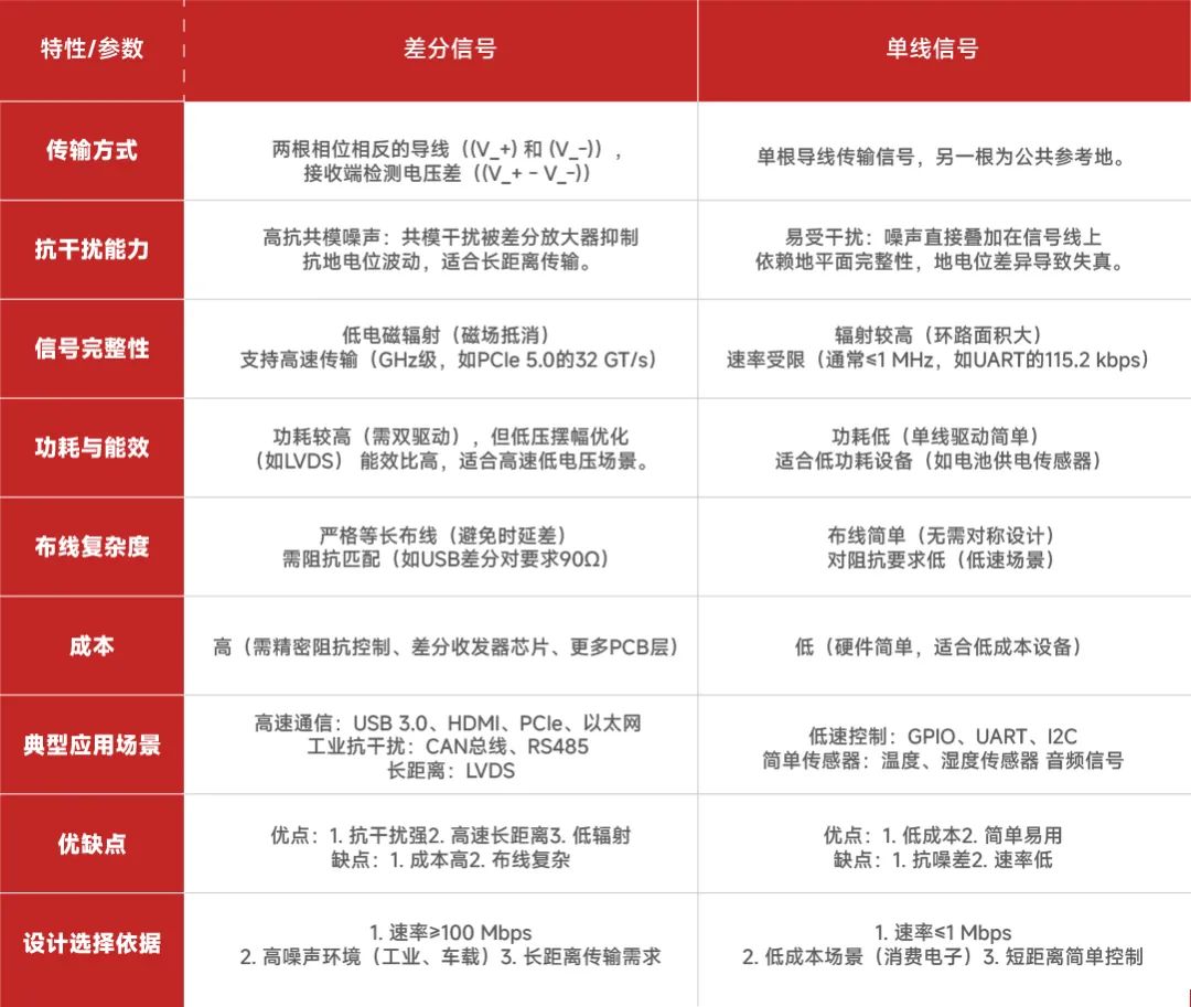
Differential signal/single-line signal
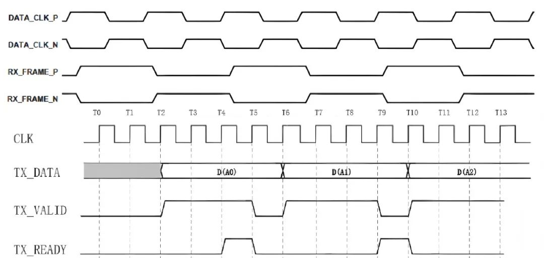
Differential signal/common mode signal
Differential transmission is a signal transmission technology. Different from the traditional practice of one signal line and one ground line, differential transmission transmits signals on both lines. The two signals have the same amplitude and opposite phase. The signal transmitted on these two lines is a differential signal. The signal receiving end compares the difference between the two voltages to determine the logical state sent by the sending end. On the circuit board, the differential traces must be two lines of equal length, equal width, close proximity, and on the same layer.
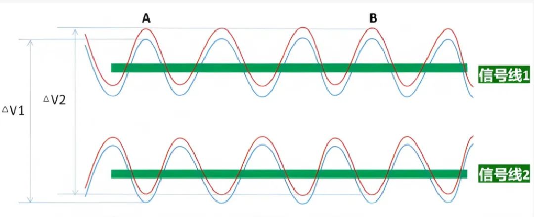
Common mode signals are the same signals acting on the same phase and opposite phase input ends of differential amplifiers or instrumentation amplifiers. For example, the noise voltage introduced to the two balanced ends of a balanced line pair. Another example is the DC voltage applied to the balanced line (for example: the DC level generated by the ground potential difference between the signal source and the receiver).
Any two signals can be decomposed into common mode signals and differential mode signals. Common mode signals are the same signals acting on the two input ends of a differential amplifier or instrumentation amplifier. They are usually generated by line conduction and spatial magnetic field interference. They are undesirable signals. Differential mode signals are signals at the two input ends that differ by 180 degrees in phase. If the common-mode signal is amplified a lot, it will affect the differential-mode signal that really needs to be amplified.
The differential-mode signal is the core functional carrier of the circuit and needs to be filtered to preserve its integrity; the common-mode signal is the main source of EMI and needs to be completely suppressed through isolation, shielding and filtering;
Co-design: Combining differential-mode and common-mode suppression measures (such as π-type filters) and optimizing PCB layout and grounding are the key to achieving high-reliability EMC design.
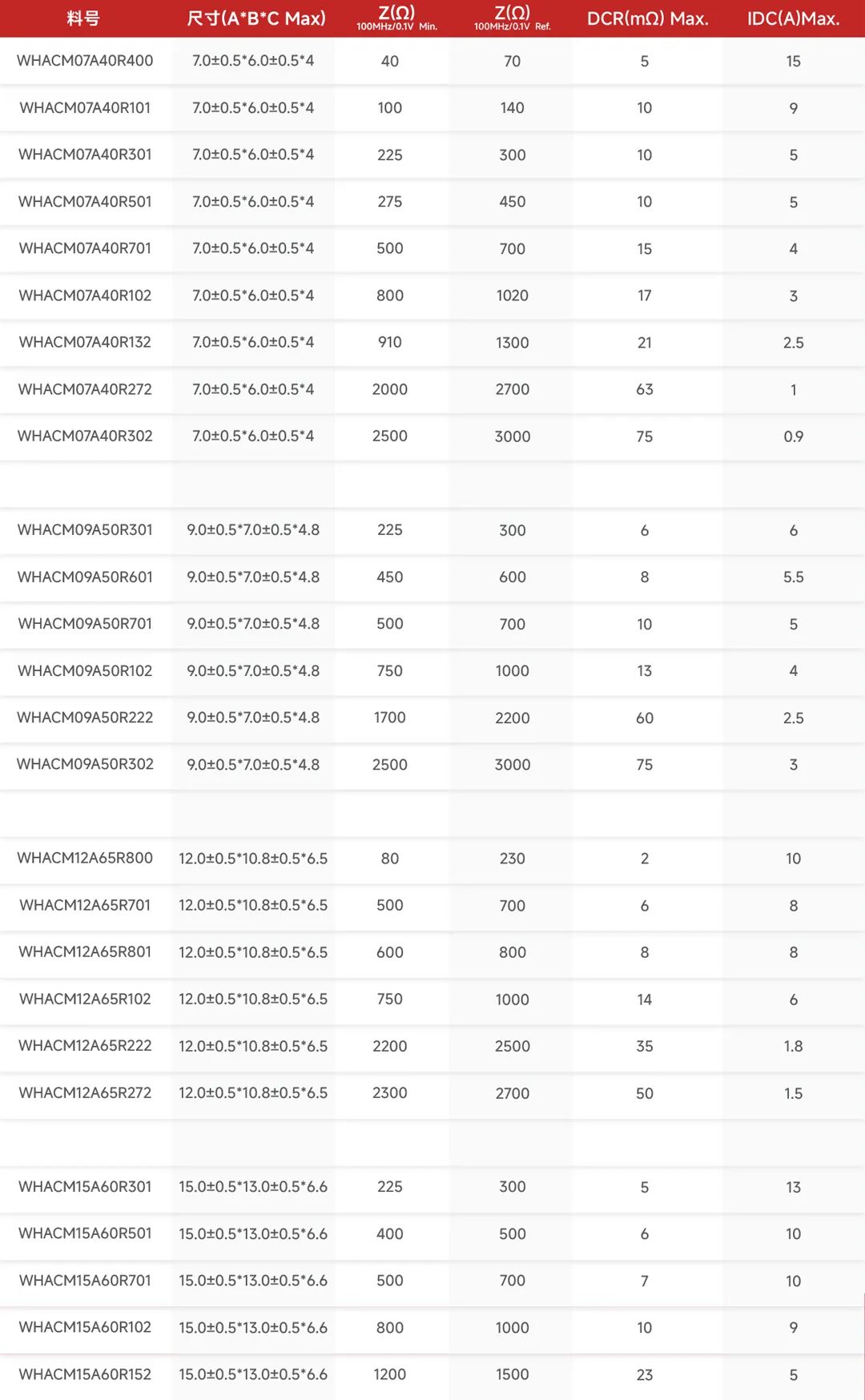
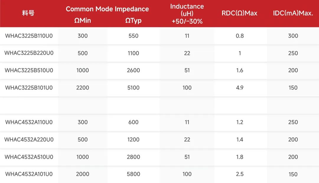
PARAMETERS
APPLICATION SCENARIO
(1) 10/100Mbps PHY
Application scenarios:
Industrial control: PLC, sensor network (such as Modbus TCP)
Smart home: smart socket, low-power IoT device (such as Zigbee gateway)
Onboard diagnostics: OBD-II interface (100BASE-T1)
(2) 1Gbps PHY
Application scenarios:
Consumer electronics: 4K TV, NAS storage
Industrial camera: machine vision (real-time image transmission)
Enterprise network: Gigabit switch, router
(3) 2.5G/5G PHY (Multi-Gigabit)
Application scenarios:
Industrial control: PLC, sensor network (such as Modbus TCP)
Smart home: smart socket, low-power IoT device (such as Zigbee gateway)
Onboard diagnostics: OBD-II interface (100BASE-T1)
(4) 10G/25G PHY
Application scenarios:
Data center: server interconnection (SFP+/QSFP28)
5G base station: fronthaul network (eCPRI over 25G)
Ultra-high-definition video production: 8K video real-time transmission
(5) 40G/100G and above PHY
Application scenarios:
AI/supercomputing cluster: GPU/TPU interconnection (InfiniBand replacement)
Core backbone network: metropolitan area network/inter-data center interconnection
Optical communication: CPRI/OBSAI fiber fronthaul
GROWTH DRIVERS
Differential signal communication system
Differential signal transmission relies on two conductors with opposite phases. Common-mode inductors can effectively suppress common-mode noise and improve signal integrity:
Ethernet
In the differential line pairs (such as RJ45 interface) of Gigabit Ethernet (such as 1000BASE-T), common-mode inductors filter out high-frequency common-mode noise to ensure the stability of high-speed data transmission.
USB (Universal Serial Bus)
The D+/D- differential pairs of USB 2.0/3.0 use common-mode inductors to suppress common-mode interference introduced by the power supply or external environment and prevent data transmission errors.
HDMI/DisplayPort
In the differential signal lines (such as TMDS channels) of high-speed video interfaces, common-mode inductors reduce high-frequency radiation interference and improve electromagnetic compatibility (EMC).
LVDS (Low Voltage Differential Signal)
In display interfaces (such as LCD and OLED drive circuits), common-mode inductors suppress common-mode noise between the display driver chip and the motherboard.
Industrial and vehicle communications
The electromagnetic interference (EMI) in industrial and vehicle environments is complex, and common-mode inductors are used to protect communication buses:
CAN bus (Controller Area Network)
In vehicle-mounted CAN bus, common-mode inductors filter out common-mode noise generated by engine ignition, motor drive, etc., to ensure the reliability of key control signals.
RS485/RS422
In industrial long-distance communications, common-mode inductors prevent ground potential differences and common-mode noise interference, and improve anti-interference capabilities. Industrial Ethernet (Profinet, EtherCAT)
In industrial automation networks, common-mode inductors suppress the impact of high-frequency noise from motors, inverters and other equipment on communications.
Wireless communication module
Wireless communication systems have extremely high requirements for signal purity. Common-mode inductors are used in radio frequency (RF) circuits:
Wi-Fi/Bluetooth modules
In antenna feed lines and RF circuits, common-mode inductors suppress common-mode interference and reduce signal distortion and bit error rate.
Cellular communication (4G/5G modules)
In antenna circuits of base stations and mobile devices, common-mode inductors reduce the interference of high-frequency noise on RF signals.
Mixed power and signal systems
In systems where power and signals coexist, common-mode inductors isolate noise paths:
PoE (Power over Ethernet)
In Ethernet power supply systems, common-mode inductors filter out common-mode noise from both power and data to avoid mutual interference.
DC/DC converters
At the input/output end of a switching power supply, common-mode inductors suppress high-frequency switching noise from coupling to communication lines through power lines.
High-speed digital circuits
High-speed digital signals are susceptible to common-mode noise, and common-mode inductors are used for key signal lines:
PCIe (high-speed serial bus)
In the differential signal lines of the PCIe interface, common-mode inductors reduce common-mode radiation caused by high-speed switching.
DDR memory interface
On the memory data bus, common-mode inductors suppress high-frequency noise and improve timing stability.
Global market size: approximately US$1.2 billion in 2023, with a compound annual growth rate (CAGR) of 6.5% (2024-203)
Growth drivers:
Surge in demand for 5G communications, new energy vehicles, and industrial automation
Tighter EMC regulations in various countries
Regional market distribution
Fields Market share Typical scenarios
Consumer electronics 35% Mobile phones, computers (USB/HDMI interfaces)
Automotive electronics 30% New energy vehicles (electric drive systems, vehicle networks)
Industry and energy 25% Inverters, photovoltaic inverters, PLC control
Communication infrastructure 10%Base stations, data centers, fiber optic equipment
Price range
Consumer grade: 0.1~0.5 USD/piece (such as chip inductors for USB interfaces)
Industrial grade: 0.5~2 USD/piece (high voltage resistance, wide temperature range models)
Automotive grade: 2~10 USD/piece (AEC-Q200 certified, such as TDK ACT45 series)
Agency business
New energy vehicle electric drive system (common mode inductors for SiC modules)
Data center high-speed optical modules (100G/400G Ethernet inductors)
Market demand forecast
New energy vehicles: demand for common mode inductors for vehicles will exceed 200 million in 2025
5G base stations: 20-30 high-frequency inductors are required for a single base station, with an annual global demand of more than 500 million

PRODUCT FEATURES

Functions of common-mode inductors
1. Suppress common-mode noise
Common-mode noise: refers to interference signals of the same direction and amplitude that exist simultaneously between two conductors (such as power lines and signal lines) in a circuit and the ground (or reference plane). Working principle: Common-mode inductors present high impedance to common-mode currents, offset common-mode noise energy through magnetic field coupling of the magnetic core, and reflect it back to the source or convert it into heat consumption.
2. Provide high-frequency impedance paths
Within the frequency range of common-mode noise (usually tens of kHz to hundreds of MHz), the high impedance characteristics of inductors can block the noise propagation path and prevent it from radiating through cables or circuits.
3. Isolate interference
Prevent external interference (such as power grid surges and radio frequency interference) from entering the system through power lines or signal lines, while suppressing the external radiation of internal noise in the system.
4. Maintain differential signal integrity
The impedance to differential signals (useful signals) is extremely low, and its transmission characteristics are almost not affected.
Differential signal/single-line signal


Differential signal/common mode signal
Differential transmission is a signal transmission technology. Different from the traditional practice of one signal line and one ground line, differential transmission transmits signals on both lines. The two signals have the same amplitude and opposite phase. The signal transmitted on these two lines is a differential signal. The signal receiving end compares the difference between the two voltages to determine the logical state sent by the sending end. On the circuit board, the differential traces must be two lines of equal length, equal width, close proximity, and on the same layer.
Common mode signals are the same signals acting on the same phase and opposite phase input ends of differential amplifiers or instrumentation amplifiers. For example, the noise voltage introduced to the two balanced ends of a balanced line pair. Another example is the DC voltage applied to the balanced line (for example: the DC level generated by the ground potential difference between the signal source and the receiver).
Any two signals can be decomposed into common mode signals and differential mode signals. Common mode signals are the same signals acting on the two input ends of a differential amplifier or instrumentation amplifier. They are usually generated by line conduction and spatial magnetic field interference. They are undesirable signals. Differential mode signals are signals at the two input ends that differ by 180 degrees in phase. If the common-mode signal is amplified a lot, it will affect the differential-mode signal that really needs to be amplified.
The differential-mode signal is the core functional carrier of the circuit and needs to be filtered to preserve its integrity; the common-mode signal is the main source of EMI and needs to be completely suppressed through isolation, shielding and filtering;
Co-design: Combining differential-mode and common-mode suppression measures (such as π-type filters) and optimizing PCB layout and grounding are the key to achieving high-reliability EMC design.

PARAMETERS


APPLICATION SCENARIO

(1) 10/100Mbps PHY
Application scenarios:
Industrial control: PLC, sensor network (such as Modbus TCP)
Smart home: smart socket, low-power IoT device (such as Zigbee gateway)
Onboard diagnostics: OBD-II interface (100BASE-T1)
(2) 1Gbps PHY
Application scenarios:
Consumer electronics: 4K TV, NAS storage
Industrial camera: machine vision (real-time image transmission)
Enterprise network: Gigabit switch, router
(3) 2.5G/5G PHY (Multi-Gigabit)
Application scenarios:
Industrial control: PLC, sensor network (such as Modbus TCP)
Smart home: smart socket, low-power IoT device (such as Zigbee gateway)
Onboard diagnostics: OBD-II interface (100BASE-T1)
(4) 10G/25G PHY
Application scenarios:
Data center: server interconnection (SFP+/QSFP28)
5G base station: fronthaul network (eCPRI over 25G)
Ultra-high-definition video production: 8K video real-time transmission
(5) 40G/100G and above PHY
Application scenarios:
AI/supercomputing cluster: GPU/TPU interconnection (InfiniBand replacement)
Core backbone network: metropolitan area network/inter-data center interconnection
Optical communication: CPRI/OBSAI fiber fronthaul
GROWTH DRIVERS
Differential signal communication system
Differential signal transmission relies on two conductors with opposite phases. Common-mode inductors can effectively suppress common-mode noise and improve signal integrity:
Ethernet
In the differential line pairs (such as RJ45 interface) of Gigabit Ethernet (such as 1000BASE-T), common-mode inductors filter out high-frequency common-mode noise to ensure the stability of high-speed data transmission.
USB (Universal Serial Bus)
The D+/D- differential pairs of USB 2.0/3.0 use common-mode inductors to suppress common-mode interference introduced by the power supply or external environment and prevent data transmission errors.
HDMI/DisplayPort
In the differential signal lines (such as TMDS channels) of high-speed video interfaces, common-mode inductors reduce high-frequency radiation interference and improve electromagnetic compatibility (EMC).
LVDS (Low Voltage Differential Signal)
In display interfaces (such as LCD and OLED drive circuits), common-mode inductors suppress common-mode noise between the display driver chip and the motherboard.
Industrial and vehicle communications
The electromagnetic interference (EMI) in industrial and vehicle environments is complex, and common-mode inductors are used to protect communication buses:
CAN bus (Controller Area Network)
In vehicle-mounted CAN bus, common-mode inductors filter out common-mode noise generated by engine ignition, motor drive, etc., to ensure the reliability of key control signals.
RS485/RS422
In industrial long-distance communications, common-mode inductors prevent ground potential differences and common-mode noise interference, and improve anti-interference capabilities. Industrial Ethernet (Profinet, EtherCAT)
In industrial automation networks, common-mode inductors suppress the impact of high-frequency noise from motors, inverters and other equipment on communications.
Wireless communication module
Wireless communication systems have extremely high requirements for signal purity. Common-mode inductors are used in radio frequency (RF) circuits:
Wi-Fi/Bluetooth modules
In antenna feed lines and RF circuits, common-mode inductors suppress common-mode interference and reduce signal distortion and bit error rate.
Cellular communication (4G/5G modules)
In antenna circuits of base stations and mobile devices, common-mode inductors reduce the interference of high-frequency noise on RF signals.
Mixed power and signal systems
In systems where power and signals coexist, common-mode inductors isolate noise paths:
PoE (Power over Ethernet)
In Ethernet power supply systems, common-mode inductors filter out common-mode noise from both power and data to avoid mutual interference.
DC/DC converters
At the input/output end of a switching power supply, common-mode inductors suppress high-frequency switching noise from coupling to communication lines through power lines.
High-speed digital circuits
High-speed digital signals are susceptible to common-mode noise, and common-mode inductors are used for key signal lines:
PCIe (high-speed serial bus)
In the differential signal lines of the PCIe interface, common-mode inductors reduce common-mode radiation caused by high-speed switching.
DDR memory interface
On the memory data bus, common-mode inductors suppress high-frequency noise and improve timing stability.
share to
Related links
You may also like
Prev article
Next article
Newsletter subscription
Subscribe to our newsletter and stay updated on the latest information of our company and product.
Name
|
Subscribe
I agree that the information that I provide will be used in accordance with the terms of Voohu International Inc. Privacy & Cookies Policy


