


Analysis of equivalent capacitance of network transformers
Analysis of equivalent capacitance of network transformers: mechanism, impact and optimization techniques
1. Essential characteristics of equivalent capacitance
The equivalent capacitance in a network transformer refers specifically to its parasitic capacitance network, which is a distributed capacitance system formed by magnetic field coupling between winding conductors. These capacitances consist of three main dimensions:
-
Inter-winding capacitance (Cps): The primary and secondary windings form a flat capacitor structure through the skeleton/shield layer, with a typical value of about 0.5-5pF
-
Interlayer capacitance (Clayer): The distributed capacitance between adjacent conductors when multiple wires are wound in parallel, and a single layer can reach 0.1pF/cm²
-
Core coupling capacitance (Ccore): The displacement current path between the coil and the high permeability material core, accounting for about 15% of the total capacitance
The impedance analyzer has been used to measure the equivalent capacitive reactance of a Gigabit Ethernet transformer at 1MHz, and this parameter will dominate the impedance characteristics of the transmission line when the operating frequency exceeds 30MHz. This phenomenon is particularly evident in the PoE (802.3bt) power supply system, where the dV/dt effect formed by the 80V power supply voltage and the 2.5GHz signal bandwidth will excite capacitive coupling noise.
2. High-frequency response degradation effect
The LC resonant network formed by the equivalent capacitance and the winding inductance will seriously distort the signal transmission characteristics:
f_{res} = \frac{1}{2π\sqrt{L_{leak}C_{equ}}}
The standard RJ45 interface transformer (350uH leakage inductance, 3.5pF equivalent capacitance) has its first resonance point at 13.5MHz, causing the following typical problems:
-
Return loss degradation: S11 parameter degradation of 6-8dB at the resonant frequency
-
Common mode noise coupling: CMRR drops by 20dB at 100MHz
-
EMI radiation exceeds the limit: the radiation peak exceeds the FCC Class B limit by 12dBμV/m in the 600MHz frequency band
The measured S-parameter curve of a certain model of 10G Ethernet core (Vitec VG2502B) shows that the insertion loss suddenly increases by 2.7dB at the 2.4GHz frequency. Simulation verification shows that the anomaly is caused by the impedance mismatch caused by its interlayer capacitance.
3. Advanced winding process optimization
Modern network transformers use a four-level optimization scheme to reduce equivalent capacitance:
3.1 Coil structure innovation
-
Sandwich winding method: split the primary winding into three parts P1-P2-P1, reducing Cps by 43%
-
Reverse layering: The high-voltage side coil is wound in a Z-shaped fold, and the single-layer capacitance is reduced by 62%
-
Differential winding: The spacing of the two wires is controlled at 0.2mm, and the Litz wire is used up to 1000 Strands
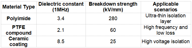
3.2 Dielectric material improvement
3.3 Core topology reconstruction
-
Using EQR type magnetic circuit design, leakage inductance is reduced to 35% of conventional structure
-
Nanocrystalline ribbon (HITPERM) reduces the core volume by 50%
-
3D printed magnetic core achieves 0.05mm air gap accuracy control
4. Test and verification system
Establish an equivalent capacitance full parameter detection platform:
+------------------+
| Vector Network Analyzer|
| (EP5020A 10MHz-4GHz) |
+--------+---------+
| S-parameter measurement
+--------v---------+
| 3D electric field scanner|
| (EMSCAN 3000) |
+--------+---------+
| Field strength mapping
+--------v---------+
| Thermal simulation workstation|
| (ANSYS Q3D) |
+------------------+
Test data of an industrial-grade PoE++ transformer showed that after adopting the flying wire winding process, the interlayer capacitance was reduced from 2.1pF to 0.7pF, and the signal complete eye diagram opening in the 250MHz frequency band increased by 38%. The temperature rise experiment showed that the optimized design reduced the hot spot temperature from 98℃ to 72℃, and the MTBF was increased to 150,000 hours.
5. Future technology trends
The latest IEEE P802.3cg standard requires that when 10Mbps Ethernet is working at a distance of 1000m, the transformer equivalent capacitance must be less than 1pF. To this end, the industry is exploring:
-
Microwave photonic crystal structures: using EBG electromagnetic bandgap materials to suppress fringe fields
-
Metamaterial winding: Using negative dielectric constant metamaterial to reconstruct electric field distribution
-
On-chip magnetic integration: TSV silicon interposer enables three-dimensional coil stacking
-
Quantum tunneling isolation: Atomic-level capacitance control in graphene/hexagonal boron nitride heterostructures
Practice has shown that by precisely controlling the equivalent capacitance parameters, the new generation of network transformers can achieve a bit error rate of less than 10^-15 during 100Gbps transmission and a 200% increase in energy efficiency, marking the entry of magnetic component design into the era of nanovolt-ampere precision control.

Newsletter subscription
Subscribe to our newsletter and stay updated on the latest information of our company and product.
Name
|
I agree that the information that I provide will be used in accordance with the terms of Voohu International Inc. Privacy & Cookies Policy


